Foot Traffic Counting
Camera Installation
Section titled “Camera Installation”Location
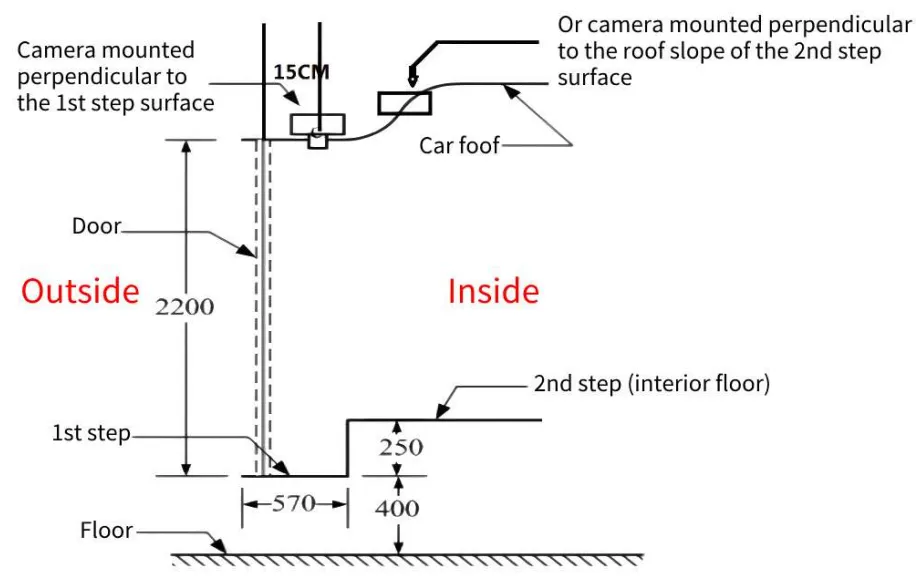
Section titled “Location”- The camera must be installed at least 15 cm away from the vehicle door.
- For the installation location, refer to the positions shown in the figure below, or install the camera on the roof as shown in the figure, provided that the ground level and the camera height are both approximately 2.1 meters.
- The dual-lens cameras of the dual-lens people counter should be installed as vertically as possible relative to the ground; the angle of inclination relative to the ground can be adjusted within 15°. The view should cover less than one-third of the exterior of the vehicle or focus entirely on the interior. (Loosen the Allen screw on the camera bracket to adjust the camera angle.)
Direction
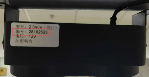
Section titled “Direction”- Camera orientation is pre-set at the factory: The label on the camera faces the interior of the vehicle.
Wiring Method
Section titled “Wiring Method”| Connector Type | Connector/Pin Order | Wiring Instructions | Notes |
|---|---|---|---|
| Power Connector | DC 8-36V | Red wire: Constant power 8-36V Yellow wire: ACC ignition signal (connect to ignition switch) Black wire: GND ground | If ACC is not connected, you can connect the ACC wire in parallel with the red power wire |
| Video Input Interface | AV IN2 | Connect front door camera | Must connect front door camera; use a video extension cable |
| Video Input Interface | AV IN4 | Connect rear door camera | Must connect rear door camera; use a video extension cable |
| I/O Wires | SENSOR 1.2.3.4.5 | I/O port configuration must match the actual connected signals | Detects door-opening signals only |
| Antenna Connectors | 4G Antenna Connector | Connects to 4G antenna | Must be installed |
| Antenna Connectors | GPS Antenna Connector | Connects to GPS antenna | Must be installed |
| Other Interfaces | 12V GND | Power output | Generally not connected |
| Communication Interfaces | RX/TX | RS-232 cable | Connect as needed based on device requirements |
| Communication Interfaces | 485A/485B | RS-485 cable | Connect as needed based on device requirements |
Device IO Configuration
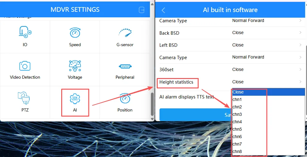
Section titled “Device IO Configuration”- Models supporting foot traffic counting algorithms: MC908, MC904, MC912
- The host version must be one that supports foot traffic counting
- Select the channel where the connected camera is located for the foot traffic counting algorithm
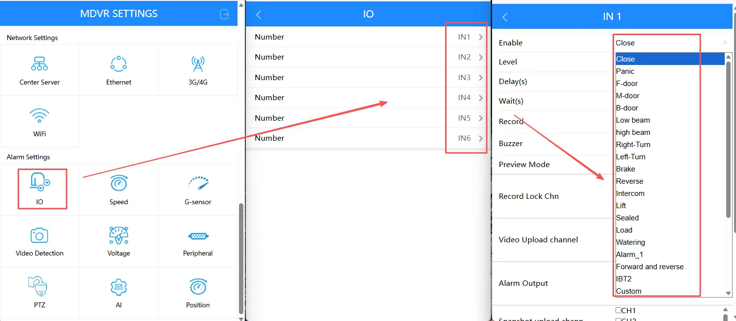
- In IO Alarms, configure the actual trigger events for each connected IO sensor; no fixed configuration is required
Software Configuration
Section titled “Software Configuration”Software installation package for foot traffic counting
-
Connect to the device’s Wi-Fi; the default password is 88888888.
-
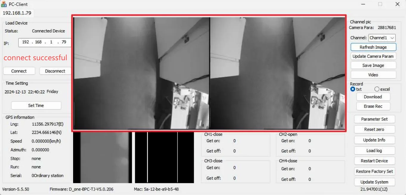
Connect the software to the device: The device’s default IP is
192.168.10.202. Clickconnect.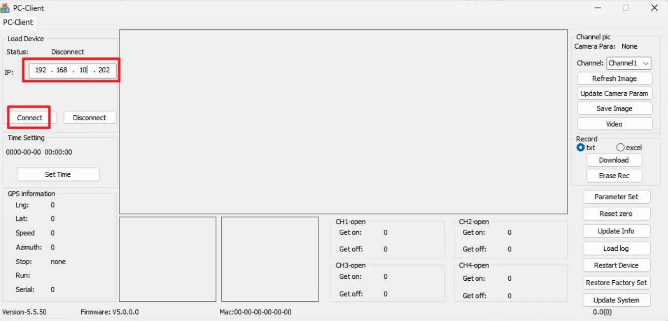
-
Explanation of Main Software Parameters
Parameters Related to Foot Traffic Statistics
Parameter Description Set Time Can be modified Update Camera Param Modify camera parameters; must be set to match the number on the camera label -
Adjust the camera angle: Ensure that the view shows less than one-third of the area outside the vehicle or focuses entirely on the interior.
-
Save background information (
Refresh Image)- It takes 2 seconds to learn the background; a success message will appear on the client.
- Save the background image for each channel separately.
- Save the background image when the door is open, ensuring there are no moving objects and the camera is not obstructed, to guarantee accuracy.
- Confirm that the image changes from gray to completely black after the background is saved.
-
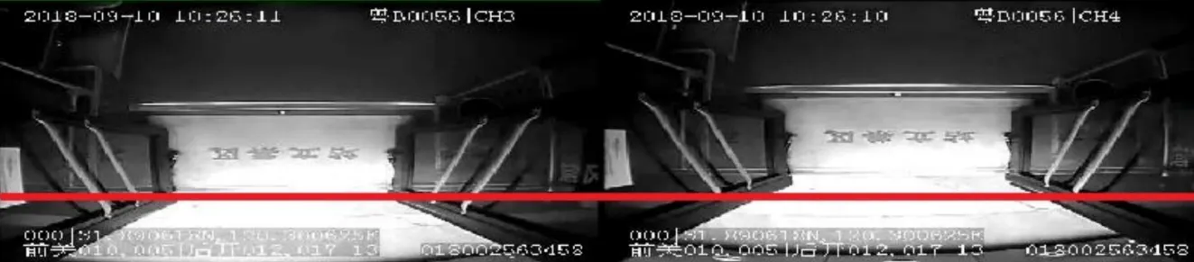
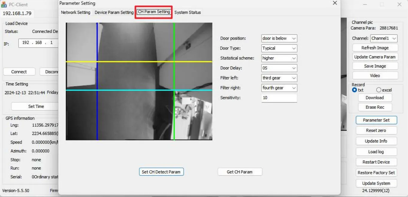
Door opening/closing parameter settings: Click
Parameter Setto adjust the calibration lines based on the installation configuration.- Only the rectangular area defined by the four lines is considered the valid detection zone. People entering from the light blue line and crossing the yellow line are identified as boarding; those entering from the yellow line and crossing the light blue line are identified as alighting. People entering or exiting to the left of the dark blue line or to the right of the green line are considered invalid and will not be counted in the boarding/alighting statistics.
-
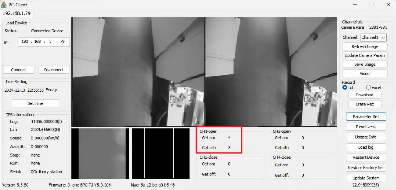
You can view boarding and alighting counts in the marked area
Viewing Foot Traffic Statistics Reports on the Platform
Section titled “Viewing Foot Traffic Statistics Reports on the Platform”-
Go to the Fleet section from the
IOTsection.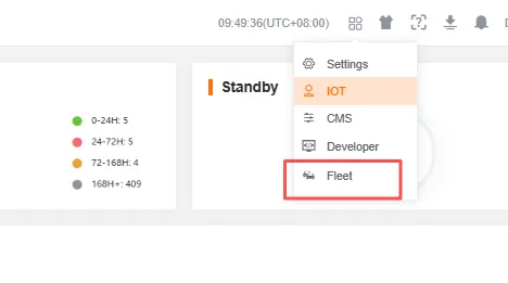
-
Click
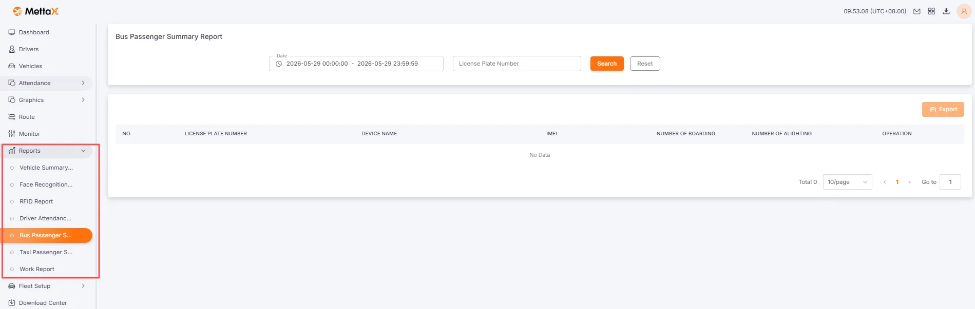
Reportsto view foot traffic statistics reports